Attenuated Total Reflectance (ATR)
$99 Base price View My Quote RequestWide Area 3D Patterned Light Measurement (VR)
This technique supports Live View
Wide Area 3D / Patterned Light measurements (VR) encompass a class of optical profilometry techniques used to visualize the surface topography of larger samples.
Strengths
- Greatest scan area among optical profilometry techniques (cm scale)
- High vertical resolution ( limit < 5 um) with balanced lateral resolution ( ~5 um)
- Non-destructive analysis
Limitations
- Contour and warp will affect surface roughness analysis
- Highly transparent or specular reflective surfaces
- High aspect ratio dimensions that block the light source
Technical Specifications:
Learn More:
Example Outputs
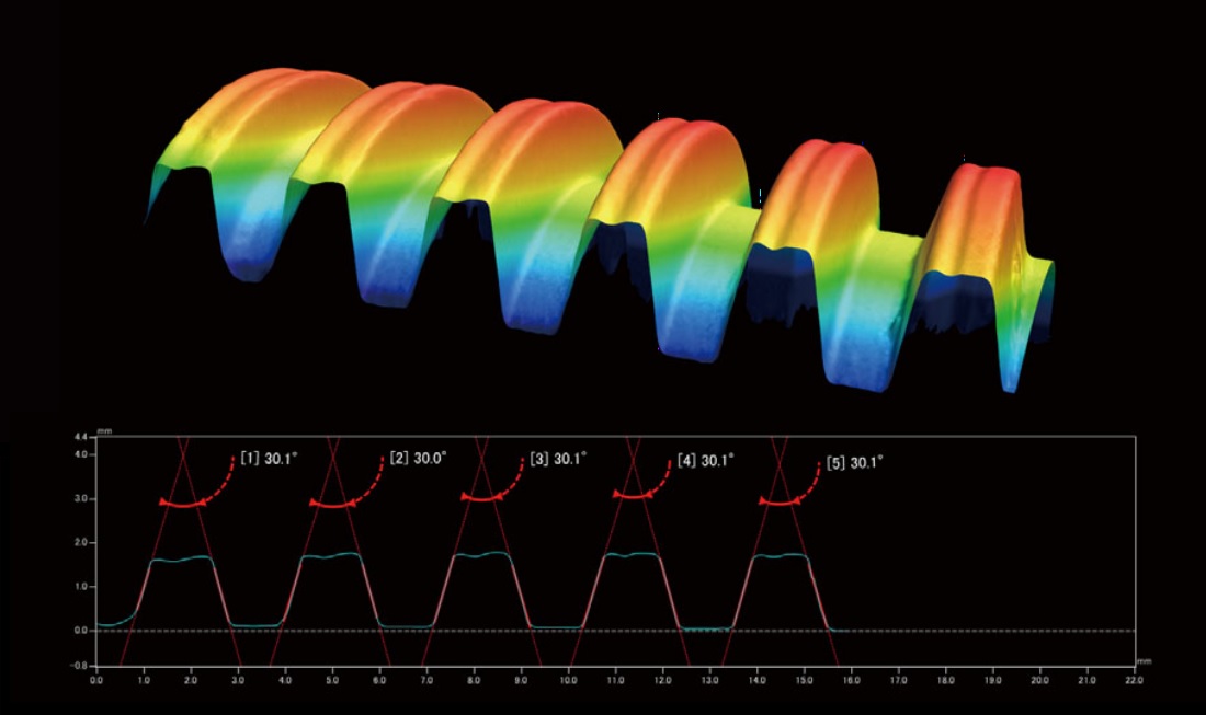
Above shows 3D model output of a trapezoidal screw scanned from single angle; below is a 2D plot showing the critical dimensions of the threads.
From Keyence

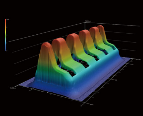
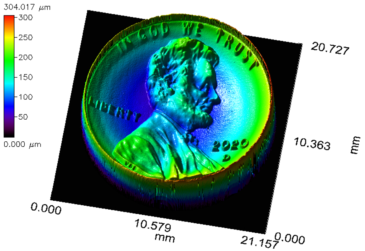
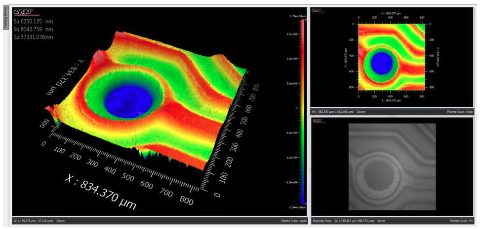
Integrated analysis of 4 different samples, showing: (in leftmost column) top-down true-color images; (in middle column) 3D CAD models generated from the original Patterned Light scans with variable color-coded topographical features – including roughness (A) and total height (C); and (in rightmost column) 2D cross-sectional plots of bump height contrasting the critical dimension of the 4 prongs in each sample.
From Keyence
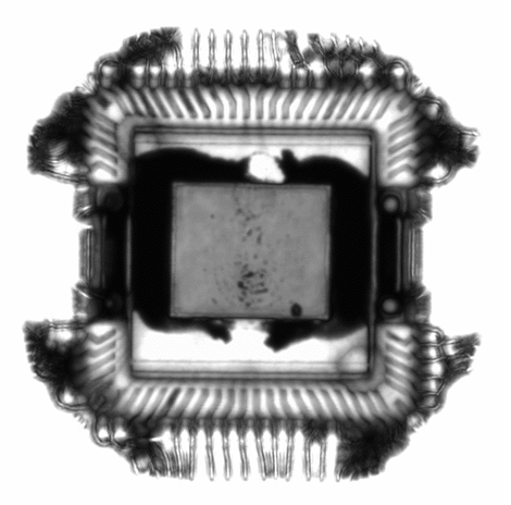
Terminal charge port connector for handheld charging dock.
From Keyence
Instruments Used for VR
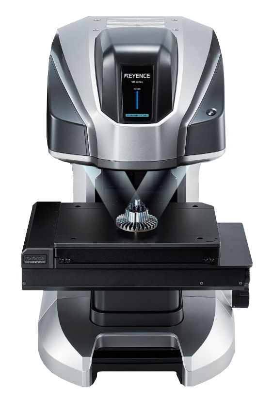
VR-5200
- One-shot 3D Measurements: generate instant 3D CAD model from single scan
- Fully automated stitching of expanded X-Y field of view
- Magnification Range: 12x to 160x
- Maximum Measurable Height Range:
- 10 mm in Wide-Field Mode (magnification up to 50x)
- 1 mm in High-Mag Mode (magnification 40x to 160x)
- Height Accuracy:
- ± 5 μm in Wide-Field Mode
- ± 2 μm in High-Mag Mode
How VR Works
In a Patterned Light measurement, striped patterns of light are projected onto the sample at a known angle of incidence from opposing directions.
A camera mounted directly above the sample captures the distortion of the bands of light due to changes in the height of the samples surface. The measured distortions are triangulated among different patterns to generate a quantitative 3D model of the surface topography.
Unique to this technique, the generated 3D model is compatible for output as a CAD overlay for volumetric comparison in process and part evaluation.
Additional Resources

Optical Microscopy and Profilometry Services
IN Publications
July 21, 2021

Datasheet: Medical Device Characterization with the Covalent Platform
IN Publications
June 14, 2021
Overview: Mid-Range Optical Profilometry
IN Publications
June 14, 2021

Datasheet: Covalent Keyence Instrument Overview
IN Publications
May 25, 2021
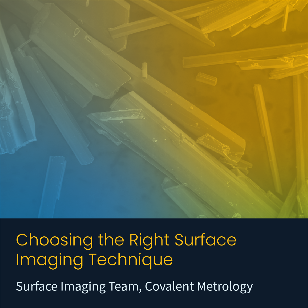
Choosing the Right Surface Imaging Technique
IN Publications
May 10, 2021
+
Add to Comparison
Digital Optical Microscopy (VH Microscope)
In Microscopy & Imaging
Optical microscopy is ubiquitous in diverse fields within academic research and commercial industries. It is an affordable, rapid...
+
Add to Comparison
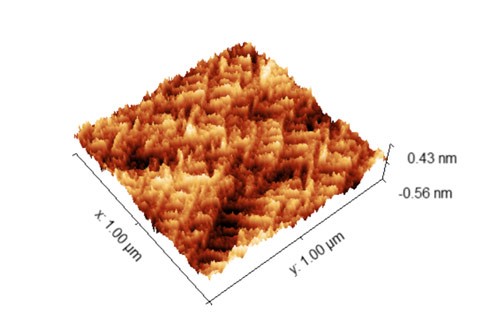
Atomic Force Microscopy (AFM)
In Material Testing
AFM measures surface topography and certain material properties with sub-nm vertical resolution and atomic-level force sensitivity.
+
Add to Comparison
Chromatic Dispersion Profilometry (CWL)
In Microscopy & Imaging
Chromatic dispersion profilometry is a non-contact, nondestructive analytical technique used to measure surface topography. It is particularly well...
+
Add to Comparison
Focused Ion Beam Scanning Electron Microscopy (FIB-SEM)
In Microscopy & Imaging
FIB-SEM systems are used to produce 2D and 3D images of surface topography, and are able to resolve...
+
Add to Comparison

Laser Scanning Confocal Microscopy (LSCM)
In Microscopy & Imaging
Laser scanning confocal microscopy (LSCM) is a nondestructive technique which generates 2D and 3D images of a sample...
+
Add to Comparison
Scanning Acoustic Microscopy (SAM)
In Microscopy & Imaging
Scanning Acoustic Microscopy (SAM) is a non-destructive and non-invasive imaging technique which uses ultrasound signals to visualize the...
+
Add to Comparison
Scanning Electron Microscopy (SEM)
In Microscopy & Imaging
Scanning electron microscopy (SEM) is a surface imaging technique capable of achieving nm resolution on topographical features. Additionally,...
+
Add to Comparison
White Light Interferometry (WLI)
In Microscopy & Imaging
White light interferometry (WLI) is a nondestructive, non-contact, optical surface topography measurement which uses coherence scanning interferometry to...
+
Add to Comparison
Wide Area 3D Patterned Light Measurement (VR)
In Failure Analysis
Wide Area 3D Patterned Light measurements encompass a class of optical profilometry techniques used to visualize the surface...
+
Add to Comparison

X-ray Computed Tomography (Micro-CT)
In Microscopy & Imaging
X-ray computed tomography (often referred to as Micro-CT due to its spatial resolution) is a non-contact, nondestructive 2D...
✕
Comparison link sent successfully
✕
Please use valid email address
✕
You need to have at least 2 techniques to compare
✕
You can select maximum 5 techniques
